Powerbank
08/12/2025
|
10 mins to read
|
Share article
I decided to start this project with the goal of developing an efficient solution to charge all my devices quickly and safely, taking advantage of the flexibility and performance of 21700 cells in a 4S configuration.
Many commercial powerbanks that actually deliver high power are considerably expensive and, on top of that, they often do not allow you to accurately monitor or control the real battery status.
Components used and cost
- 21700 cells in a 4S configuration (Samsung 50G INR21700): €12.41
- BMS: €2
- ESP32-S3 Supermini: €4
- INA228 chip: €5.09
- ST7789 display: €9
- IP2368 charger: €12.79
- MP1584 DC-DC: €2.39
- 3D printing: ≈ €1.2
- Custom PCB: €0.85
- Miscellaneous: ≈ €2
Total per unit: approximately €52
Operation and SOC calculation
To display the battery percentage on screen, it must be calculated using the data provided by the INA228 chip.
In lithium batteries, the discharge curve relative to voltage is not linear, so we cannot rely on that value alone to calculate the SOC. As shown in the following graph, the voltage starts to drop significantly below 3.4V.
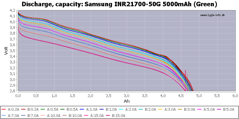
Therefore, to calculate the remaining battery percentage I used the Coulomb Counting (CC) method. This is the most widely used method in all kinds of electronic devices to calculate the State of Charge of their batteries.
Coulomb Counting is a battery State of Charge (SOC) measurement technique based on integrating the current flowing into or out of the system over time. It is calculated by summing the transferred charge according to the following relation:

Where I(t) is the instantaneous current. This method makes it possible to determine consumed or stored energy with high accuracy if the initial charge point is known. In my case, I fixed it at the maximum charge limit when the per-cell voltage is 4.2V and the charging current is 0A (BMS overcharge protection). This point tells me that the battery is fully charged and the Coulomb Counting process can begin.
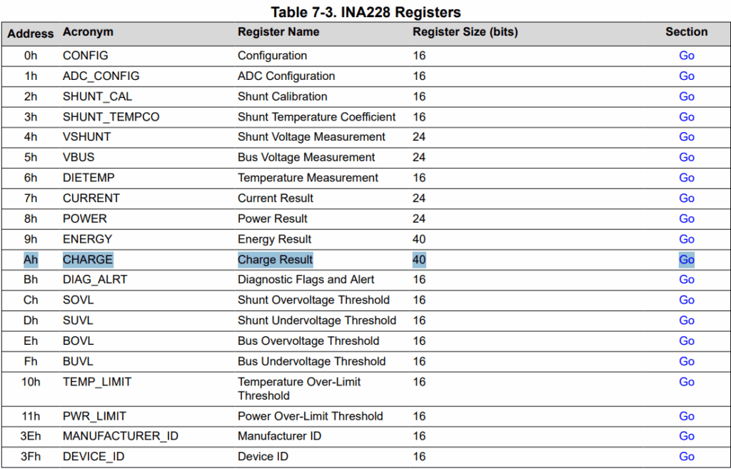
To obtain the battery SOC, the INA228 chip directly provides a register where the calculation is already performed automatically. This allows significant power savings, since the ESP32 can remain in Deep Sleep when it is not being used. According to the datasheet provided by Texas Instruments, the integral is calculated digitally through iterative accumulation. The formula used internally to calculate the SOC is:

This value is stored in the following register so it can be read by the ESP32 over I2C.
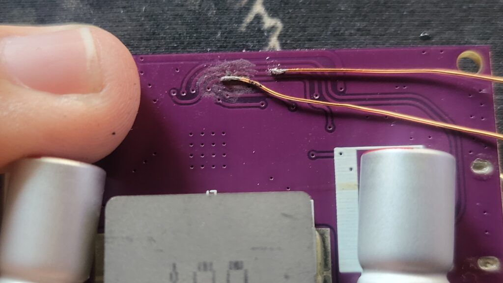
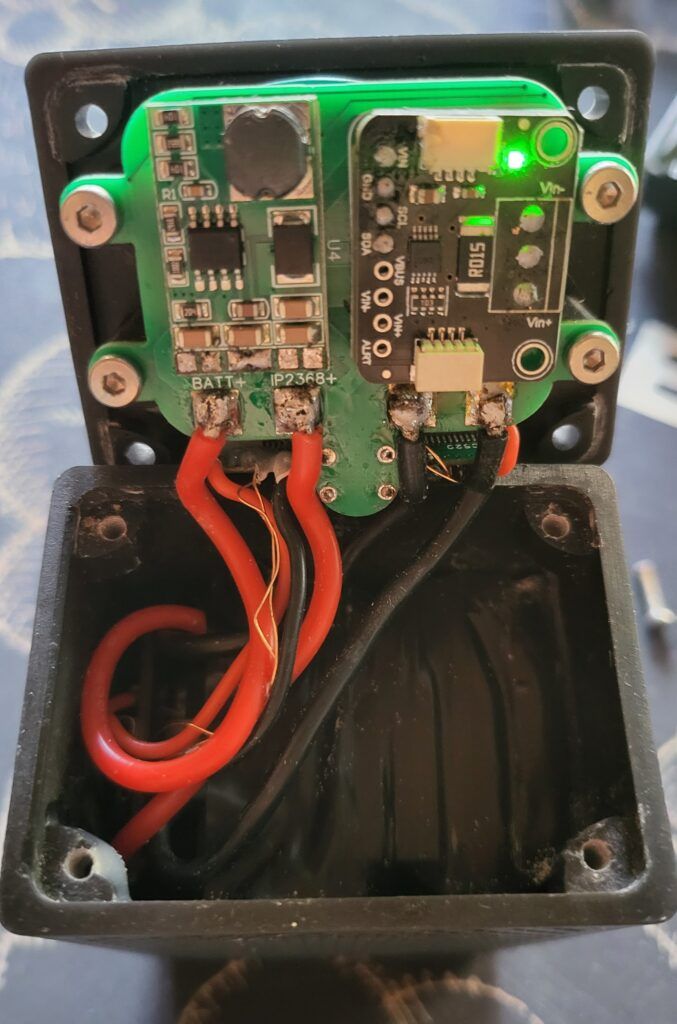
IP2368 bidirectional charger
The chip responsible for charging the batteries and providing a 100W output is the IP2368. It was chosen because it is very versatile. It allows selecting parameters through resistors such as the number of battery cells in series, charging current, and discharge current. It also provides protections such as battery overcharge, over-discharge, and over-current protection, among others.
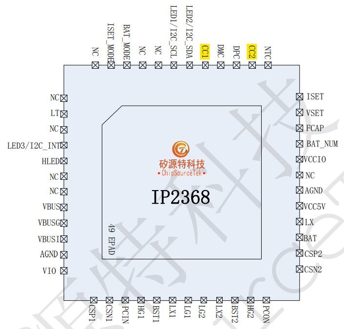
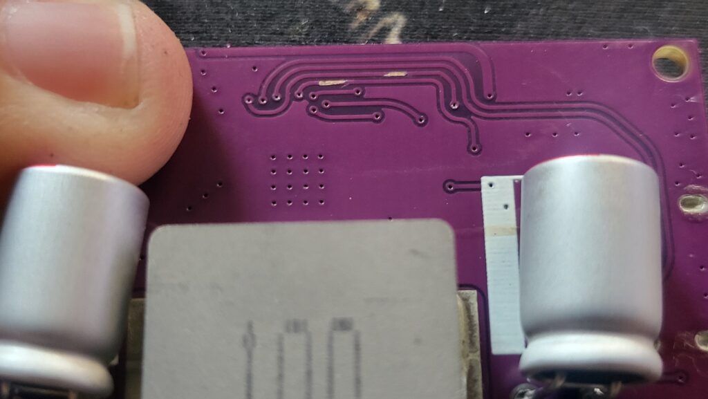
To use a USB-C port different from the one soldered onto the board, with the help of the datasheet and a multimeter it was possible to locate the required traces for the PD communication channels as well as the positive voltage line.
Once the traces were identified, small points of the solder mask were removed in order to solder 0.3 mm wire directly to the copper trace.
Construction
Battery pack creation
The batteries chosen for this project are Samsung 50G 21700 cells, which provide a capacity of 4900 mAh per cell and, in a 4S configuration, a total energy capacity of 72.5 Wh.
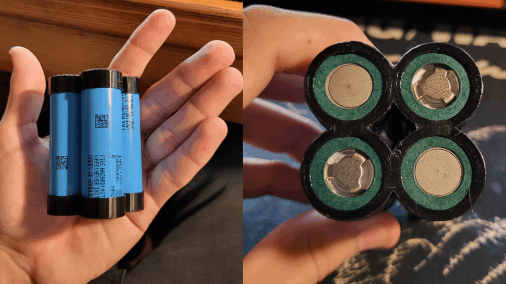
The selected BMS follows the shape of the 21700 cells to occupy as little space as possible and simplify the connections.
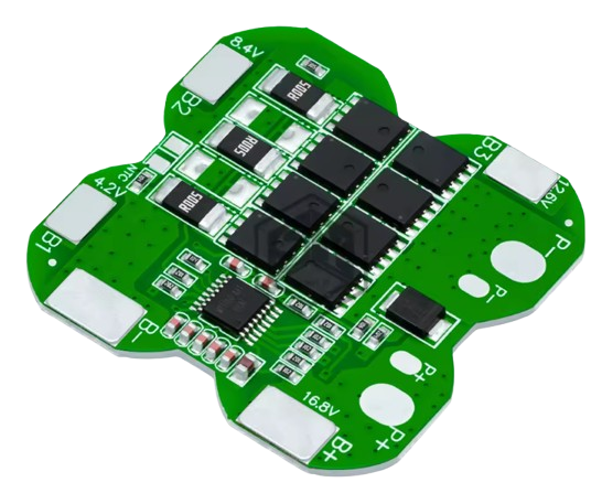
According to the manufacturer, it provides the following protections:
- Overcharge protection Protects against battery overcharging.
- Overdischarge protection Prevents the battery from discharging below the safe limit.
- Overcurrent protection Prevents excessive current flow.
- Balanced protection Balances the charge between cells to extend battery lifespan.
- Short circuit protection Automatic disconnection in the event of a short circuit.
- Temperature control protection Controls temperature to prevent overheating.
Electronic prototype
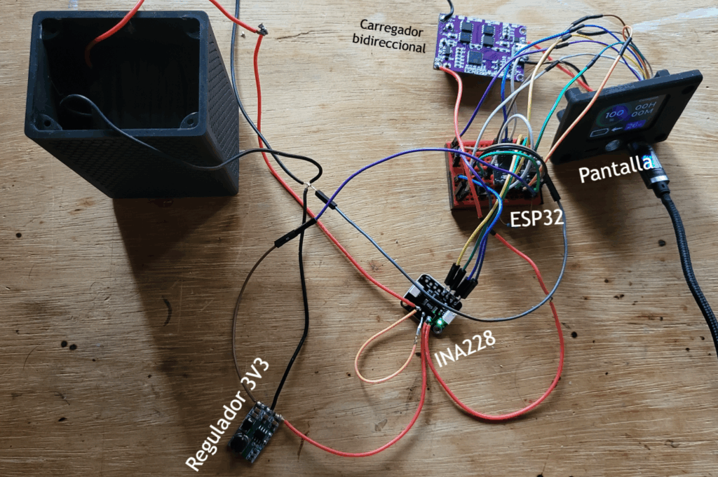
Before designing the PCB, the entire project was first assembled on a protoboard to validate the correct operation of all parts. To measure energy with the INA228 chip, the battery positive line goes through the SHUNT resistor and then to all loads (chargers/regulator). This arrangement ensures that all the battery energy is measured, allowing the displayed battery percentage to be as accurate as possible. *See code section
PCB design and creation
The PCB was designed together with the 3D model so it could be screwed onto the powerbank lid using four M3 screws, maximizing overall robustness.
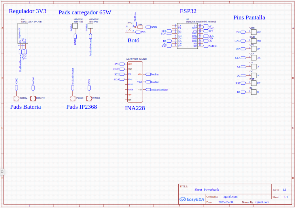
This is the PCB schematic where all connections are centralized. The INA228 is responsible for measuring the power consumed by all components, including the ESP32 and the chip itself, which ensures an accurate battery percentage.
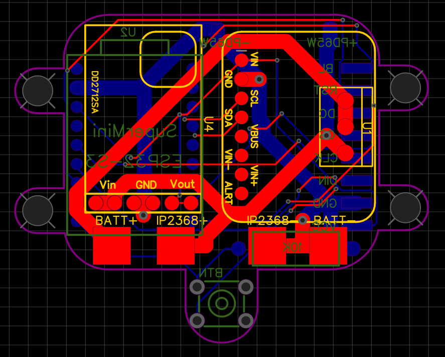
Once the components were placed and the traces carrying higher current were widened, this was the final PCB design.
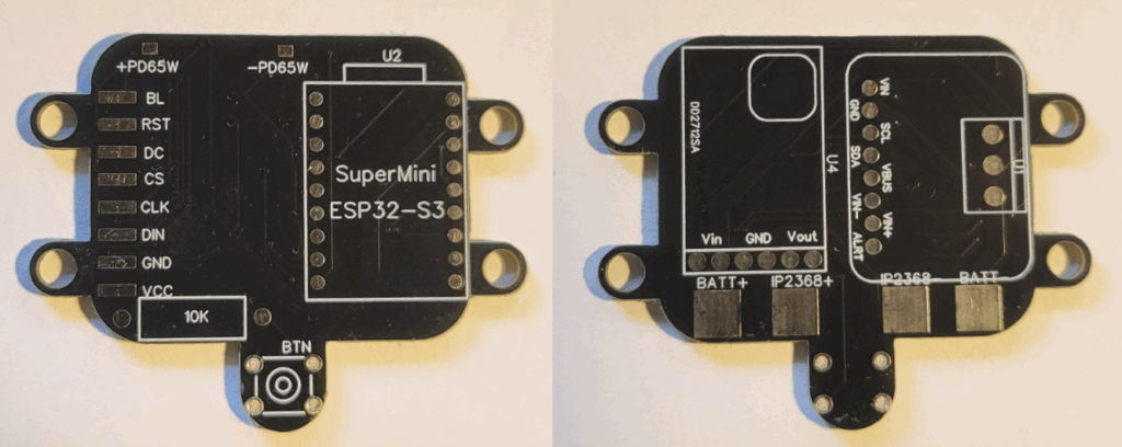
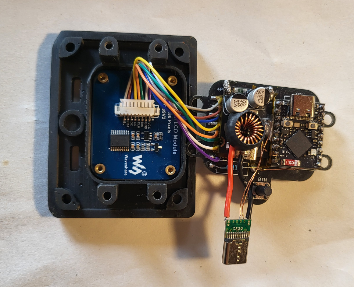
And with the components soldered:
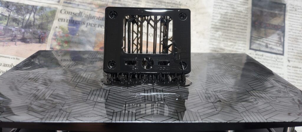
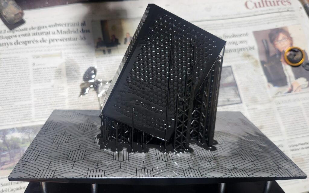
3D design and assembly
The entire 3D design was created using the software onshape.com. It consists of two main parts: the base, which contains the battery and the IP2368 charger, and the lid, which contains all the electronics.
These models were printed using a resin 3D printer.
Microcontroller programming
UI creation
The UI was created using SquareLine Studio, which allows building graphical interfaces for microcontrollers compatible with the TFT_eSPI library.
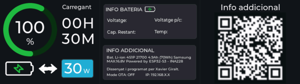
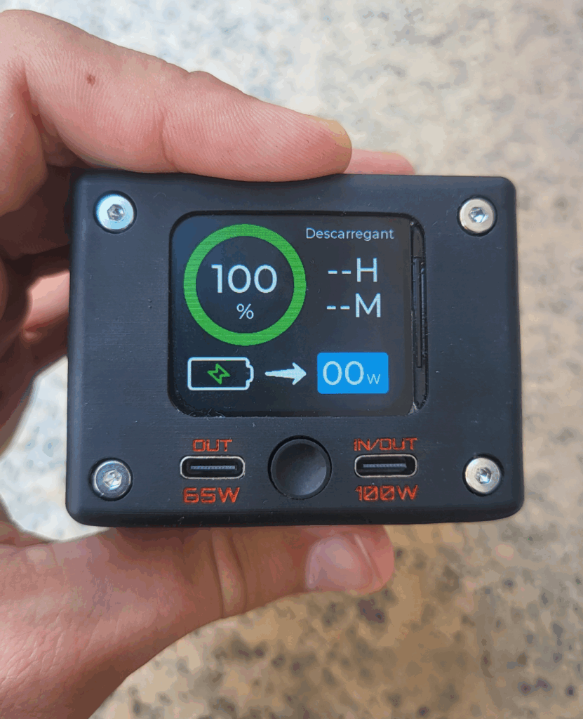
It consists of three screens that rotate cyclically each time the button is pressed. The first screen shows battery percentage, status, remaining time until charge/discharge completion, and the current power flow.
The second screen shows battery values and technical specifications of the powerbank. It also displays OTA (over-the-air programming) mode information such as the IP assigned to the microcontroller and the current status.
Finally, the last screen contains a QR code that redirects to this page.
C++ code
The code begins by declaring the libraries, variables, and initializing everything required for the LVGL library to work correctly.
#include <lvgl.h>
#include <TFT_eSPI.h>
#include <ui.h>

#include <Wire.h>
#include "INA228.h"

// OTA libraries
#include <AsyncTCP.h>
#include <ESPAsyncWebServer.h>
#include <ElegantOTA.h>
AsyncWebServer server(80);

#include "driver/rtc_io.h"
#include "esp_sleep.h"

/* Variables */
#define WAKEUP_GPIO GPIO_NUM_8

// OTA vars
      const char* ssid = "";
      const char* password = "";
      int buttonPressCount = 0;
      unsigned long lastPressTime = 0;
      const unsigned long multiClickWindow = 3000;
      bool OTAenabled = false;


int percentatgeBateria = 0;

#define DEBOUNCE_DELAY 300

unsigned long tempsAnteriorComptadorPantalla = 0;
const unsigned long intervalPantallaEncesa = 15000;
bool pantallaEngegada = false;

static unsigned long lastButtonPress = 0;

int pantallaActual = 0; // Current screen index

/* Current sensor variables */

        INA228 ina228(0x40);

        // I2C configuration
        #define SDA_PIN 2
        #define SCL_PIN 1

        // Battery parameters (adjust them according to your battery)
        const float BATTERY_CAPACITY = 4.9;          // Capacity in Ah
        const float FULL_VOLTAGE = 16.8;             // Full voltage (4S Li-ion)
        const float EMPTY_VOLTAGE = 12.6;            // Discharged voltage
        const float CHARGE_CURRENT_THRESHOLD = 0.01;  // Current threshold to consider charge/discharge

        // Status variables
        float batteryVoltage = 0.0;
        float current = 0.0;
        float charge = 0.0;
        float batteryPercentage = 100.0;
        float remainingCapacity = BATTERY_CAPACITY;  // Remaining capacity in Ah
        const int totalCharge = BATTERY_CAPACITY * 3600;                     // Total charge in Coulombs


        unsigned long lastGraphicsUpdate = 0;
        const unsigned long intervalGraphicsUpdate = 1000; // 1 second


        unsigned long lastCoulombUpdateTime = 0;

        unsigned long lastUpdatedTime = 0;

/* Pin variables */

const int iluminacioPantalla = 5;
const int boto = 8;


/* Change to your screen resolution */
static const uint16_t screenWidth  = 240;
static const uint16_t screenHeight = 280;

static lv_disp_draw_buf_t draw_buf;
static lv_color_t buf[ screenWidth * screenHeight / 10 ];

TFT_eSPI tft = TFT_eSPI(screenWidth, screenHeight); /* TFT instance */

#if LV_USE_LOG != 0
/* Serial debugging */
void my_print(const char * buf)
{
    Serial.printf(buf);
    Serial.flush();
}
#endif

/* Display flushing */
void my_disp_flush( lv_disp_drv_t *disp, const lv_area_t *area, lv_color_t *color_p )
{
    uint32_t w = ( area->x2 - area->x1 + 1 );
    uint32_t h = ( area->y2 - area->y1 + 1 );

    tft.startWrite();
    tft.setAddrWindow( area->x1, area->y1, w, h );
    tft.pushColors( ( uint16_t * )&color_p->full, w * h, true );
    tft.endWrite();

    lv_disp_flush_ready( disp );
}
In setup, all elements are initialized, such as the INA228 and the display, and all pin modes are configured.
void setup()
{
    Serial.begin( 115200 ); /* prepare for possible serial debug */
    while (!Serial) delay(10);

    pinMode(boto, INPUT);
    pinMode(iluminacioPantalla, OUTPUT);

    // Display initially off
    digitalWrite(iluminacioPantalla,LOW);


    // INA228 configuration
            Wire.begin(SDA_PIN, SCL_PIN);

            // Initialize INA228
            if (!ina228.begin()) {
                Serial.println("Error initializing INA228");
                while (1);
            }
            Serial.println("INA228 initialized correctly");

            // Sensor configuration
            ina228.setMaxCurrentShunt(10, 0.015);

    //---------------------------

    String LVGL_Arduino = "Hello Arduino! ";
    LVGL_Arduino += String('V') + lv_version_major() + "." + lv_version_minor() + "." + lv_version_patch();

    Serial.println( LVGL_Arduino );
    Serial.println( "I am LVGL_Arduino" );

    lv_init();

#if LV_USE_LOG != 0
    lv_log_register_print_cb( my_print ); /* register print function for debugging */
#endif

    tft.begin();          /* TFT init */
    tft.setRotation( 0 ); /* Landscape orientation, flipped */

    lv_disp_draw_buf_init( &draw_buf, buf, NULL, screenWidth * screenHeight / 10 );

    /* Initialize the display */
    static lv_disp_drv_t disp_drv;
    lv_disp_drv_init( &disp_drv );
    /* Change the following line to your display resolution */
    disp_drv.hor_res = screenWidth;
    disp_drv.ver_res = screenHeight;
    disp_drv.flush_cb = my_disp_flush;
    disp_drv.draw_buf = &draw_buf;
    lv_disp_drv_register( &disp_drv );

    /* Initialize the (dummy) input device driver */
    static lv_indev_drv_t indev_drv;
    lv_indev_drv_init( &indev_drv );
    indev_drv.type = LV_INDEV_TYPE_POINTER;
    indev_drv.read_cb = my_touchpad_read;
    lv_indev_drv_register( &indev_drv );


    ui_init();

    Serial.println( "Setup done" );
}

bool lastButtonState = HIGH; // Ensures the action only happens on press and release, not while held down
At the beginning of the loop, there is code responsible for reading the INA228 registers and performing the SOC calculation.
void loop()
{
    // INA228 loop

            unsigned long currentTime = millis();
            unsigned long elapsedTime = currentTime - lastCoulombUpdateTime;

            if (currentTime - lastCoulombUpdateTime >= 1000) {
            lastCoulombUpdateTime = currentTime;

            // Read sensor values
            batteryVoltage = ina228.getBusVolt();
            current = -ina228.getCurrent(); // Invert polarity in code
            charge = ina228.getCharge();


            // Coulomb counting


                // Calculate percentage based on remaining capacity
                batteryPercentage = ((totalCharge + (charge)) / totalCharge) * 100.0;

                // Limit percentage between 0 and 100
                batteryPercentage = constrain(batteryPercentage, 0.0, 100.0);

                // Update remaining capacity in Ah
                remainingCapacity = BATTERY_CAPACITY * (batteryPercentage / 100);


            // Auto-calibration when the battery is full or empty
            if (batteryVoltage >= FULL_VOLTAGE && current > -0.02 && current < 0.1) {
                batteryPercentage = 100.0;
                remainingCapacity = BATTERY_CAPACITY;

                ina228.setAccumulation(1); // When the battery reaches 100, reset the accumulated charge
                ina228.setAccumulation(0);


            } else if (batteryVoltage <= EMPTY_VOLTAGE) {
                batteryPercentage = 0.0;
                remainingCapacity = 0.0;

            }

            // Display information
            displayBatteryInfo();
            }


    //------------------------------------------------------
Next, all labels displaying data such as battery percentage, voltage, and so on are updated.
// MAIN LOOP TO UPDATE GRAPHICS. RUN EVERY 1 SECOND TO SAVE POWER
    unsigned long currentMillisGraphics = millis();

    if (currentMillisGraphics - lastGraphicsUpdate >= intervalGraphicsUpdate) {
    lastGraphicsUpdate = currentMillisGraphics;


    if (currentTime - lastUpdatedTime > 10000) {

        lastUpdatedTime = currentTime;
        updateBatteryTime(remainingCapacity, current, BATTERY_CAPACITY); // Function that updates the remaining time label for charge or discharge


    }


    updateChargingLabel(current); // Function responsible for setting charging or discharging on the label above the time

    lv_arc_set_value(uic_arcPercent, batteryPercentage);

    char buf[50];

    snprintf(buf, sizeof(buf), "%d%", (int)batteryPercentage);
    lv_label_set_text(uic_LabelPercent, buf);

    // Label showing watts
    snprintf(buf, sizeof(buf), "%02d%", (int)(ina228.getWatt()));
    lv_label_set_text(uic_ChargingWatts, buf);

    // Total voltage
    snprintf(buf, sizeof(buf), "Voltage: %.2fV", batteryVoltage);
    lv_label_set_text(uic_Voltatge, buf);

    float cellVoltage = batteryVoltage / 4.0;
    // Voltage per cell
    snprintf(buf, sizeof(buf), "Voltage p/c: %.2fV", cellVoltage);
    lv_label_set_text(uic_voltatgePerCella, buf);

    // Remaining capacity
    snprintf(buf, sizeof(buf), "Remaining cap.: %.2fAh", remainingCapacity);
    lv_label_set_text(uic_capRestant, buf);

    // Temperature
    snprintf(buf, sizeof(buf), "Temp: %.1f", ina228.getTemperature());
    lv_label_set_text(uic_temp, buf);

    }

    if(remainingCapacity > BATTERY_CAPACITY){
      remainingCapacity = BATTERY_CAPACITY;

    }
The following code checks the button state and changes screens when it is pressed. If it is pressed 5 times in a row, OTA mode is enabled, and if no interaction is detected for the last 15 seconds, the display turns off and the ESP32 enters Deep Sleep.
bool buttonState = digitalRead(boto);

 if (lastButtonState == HIGH && buttonState == LOW) {
    unsigned long currentMillis = millis();

    if (currentMillis - lastButtonPress > DEBOUNCE_DELAY) {
        tempsAnteriorComptadorPantalla = currentMillis;

        // Turn on display
        digitalWrite(iluminacioPantalla, HIGH);


        // Screen change
        if (pantallaActual == 0 && pantallaEngegada) {
            lv_scr_load_anim(ui_Screen2, LV_SCR_LOAD_ANIM_NONE, 250, 0, false);
            pantallaActual = 1;
        } else if (pantallaActual == 1 && pantallaEngegada) {
            lv_scr_load_anim(ui_Screen3, LV_SCR_LOAD_ANIM_NONE, 250, 0, false);
            pantallaActual = 2;
        } else if (pantallaActual == 2 && pantallaEngegada) {
            lv_scr_load_anim(ui_Screen1, LV_SCR_LOAD_ANIM_NONE, 250, 0, false);
            pantallaActual = 0;
        }

        pantallaEngegada = true;

        lastButtonPress = currentMillis;

        // OTA control
        if (buttonPressCount == 0) {
            lastPressTime = currentMillis;
        }

        buttonPressCount++;

        if (buttonPressCount >= 5 && (currentMillis - lastPressTime) <= multiClickWindow) {
            Serial.println("Enabling OTA mode...");
            initWiFiAndOTA();
            buttonPressCount = 0;
        } else if ((currentMillis - lastPressTime) > multiClickWindow) {
            buttonPressCount = 1; // reset if max time has elapsed
            lastPressTime = currentMillis;
        }
    }
}else{

        // When the time expires, turn off the display
        unsigned long tempsActual = millis();
        if (tempsActual - tempsAnteriorComptadorPantalla >= intervalPantallaEncesa && OTAenabled == false) {
            tempsAnteriorComptadorPantalla = tempsActual;
            digitalWrite(iluminacioPantalla,LOW);
            pantallaEngegada = false;
            // Return to the home screen
            lv_scr_load_anim(ui_Screen1, LV_SCR_LOAD_ANIM_NONE, 250, 0, false);
            pantallaActual = 0;


            sleep_until_gpio_high();
        }


  }

    lastButtonState = buttonState;  // Save the state for the next iteration

    ElegantOTA.loop();
    lv_timer_handler(); /* let the GUI do its work */
    delay(5);
}
Finally, a few helper functions are defined to improve code clarity.
void updateChargingLabel(float current) {
    static int previousChargingState = -2; // -1 = discharging, 0 = idle, 1 = charging
    int currentChargingState;

    const float threshold = 0.01;

    if (current < -threshold) {
        currentChargingState = 1; // charging
    } else if (current > threshold) {
        currentChargingState = -1; // discharging
    } else {
        currentChargingState = 0; // idle
    }

    if (currentChargingState != previousChargingState) {
        previousChargingState = currentChargingState;

        switch (currentChargingState) {
            case 1: // charging
                lv_label_set_text(uic_LabelCharging, "Charging");
                lv_obj_add_flag(uic_ArrowDischarging, LV_OBJ_FLAG_HIDDEN);
                lv_obj_clear_flag(uic_ArrowCharging, LV_OBJ_FLAG_HIDDEN);
                break;

            case -1: // discharging
                lv_label_set_text(uic_LabelCharging, "Discharging");
                lv_obj_add_flag(uic_ArrowCharging, LV_OBJ_FLAG_HIDDEN);
                lv_obj_clear_flag(uic_ArrowDischarging, LV_OBJ_FLAG_HIDDEN);
                break;

            case 0: // idle
                lv_label_set_text(uic_LabelCharging, "Idle");
                lv_obj_add_flag(uic_ArrowCharging, LV_OBJ_FLAG_HIDDEN);
                lv_obj_clear_flag(uic_ArrowDischarging, LV_OBJ_FLAG_HIDDEN);
                break;
        }
    }
}


// Function to update the label with the remaining time
void updateBatteryTime(float remainingCapacity, float current, float fullCapacity) {
  // Avoid division by zero or very small values
  if (abs(current) < 0.001) {
    lv_label_set_text(uic_LabelTime, "--H\n--M");
    return;
  }

  float hours;

  if (current < 0) {
    // We are charging -> calculate the time needed to fill the battery
    float remainingToFull = fullCapacity - remainingCapacity;

    if (remainingToFull <= 0) {
      lv_label_set_text(uic_LabelTime, "00H\n00M");  // Already full
      return;
    }

    hours = remainingToFull / abs(current);
  } else {
    // We are discharging -> calculate the time until depletion
    hours = remainingCapacity / current;
  }

  // Convert to hours and minutes
  int h = (int)hours;
  int m = (int)((hours - h) * 60);

  if (h > 100) {  // Unrealistic value -> show "--"
    lv_label_set_text(uic_LabelTime, "--H\n--M");
  } else {
    char timeText[16];
    snprintf(timeText, sizeof(timeText), "%02dH\n%02dM", h, m);
    lv_label_set_text(uic_LabelTime, timeText);
  }
}

void initWiFiAndOTA() {
  if(OTAenabled == false){
      WiFi.mode(WIFI_STA);
      WiFi.begin(ssid, password);
      Serial.print("Connecting to WiFi...");
      int retries = 0;
      while (WiFi.status() != WL_CONNECTED && retries < 20) {
        delay(500);
        Serial.print(".");
        retries++;
      }

      if (WiFi.status() == WL_CONNECTED) {
        Serial.println("\nWiFi connected: " + WiFi.localIP().toString());
        server.on("/", HTTP_GET, [](AsyncWebServerRequest *request){
          request->send(200, "text/plain", "Powerbank OTA Ready");
        });

      } else {
        Serial.println("\nCould not connect to WiFi");
      }


      server.begin();
      ElegantOTA.begin(&server);
      OTAenabled = true;
      Serial.println("OTA Enabled");

      char buf1[50];
      snprintf(buf1, sizeof(buf1), "OTA Mode: ON          IP: %s", WiFi.localIP().toString());
      lv_label_set_text(uic_OTA, buf1);

    }else{
      server.end();
      WiFi.disconnect(true);
      WiFi.mode(WIFI_OFF);
      Serial.println("OTA Disabled");
      OTAenabled = false;

      char buf1[50];
      snprintf(buf1, sizeof(buf1), "OTA Mode: OFF          IP: 192.168.X.X");
      lv_label_set_text(uic_OTA, buf1);
    }


}

void sleep_until_gpio_high() {
  rtc_gpio_pullup_dis(WAKEUP_GPIO);
  rtc_gpio_pulldown_en(WAKEUP_GPIO);
  esp_sleep_enable_ext0_wakeup(WAKEUP_GPIO, 1);  // 1 = wake up on HIGH

  delay(100);  // Give time to print

  esp_light_sleep_start();
}
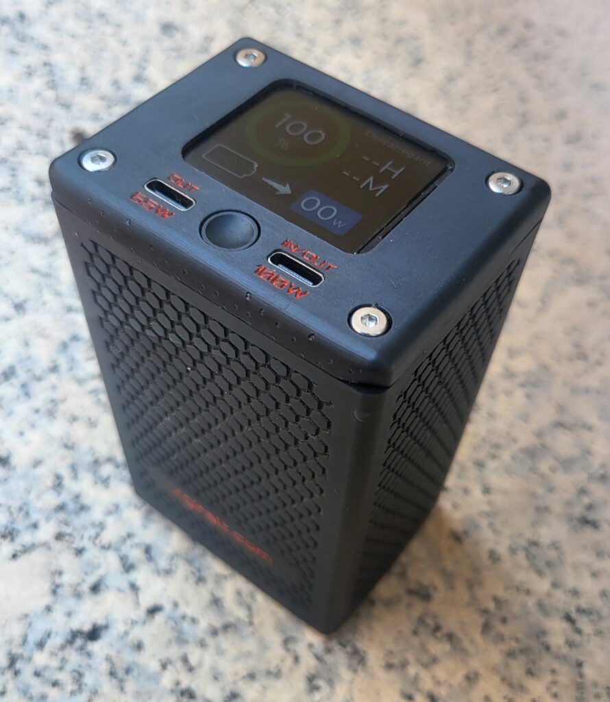
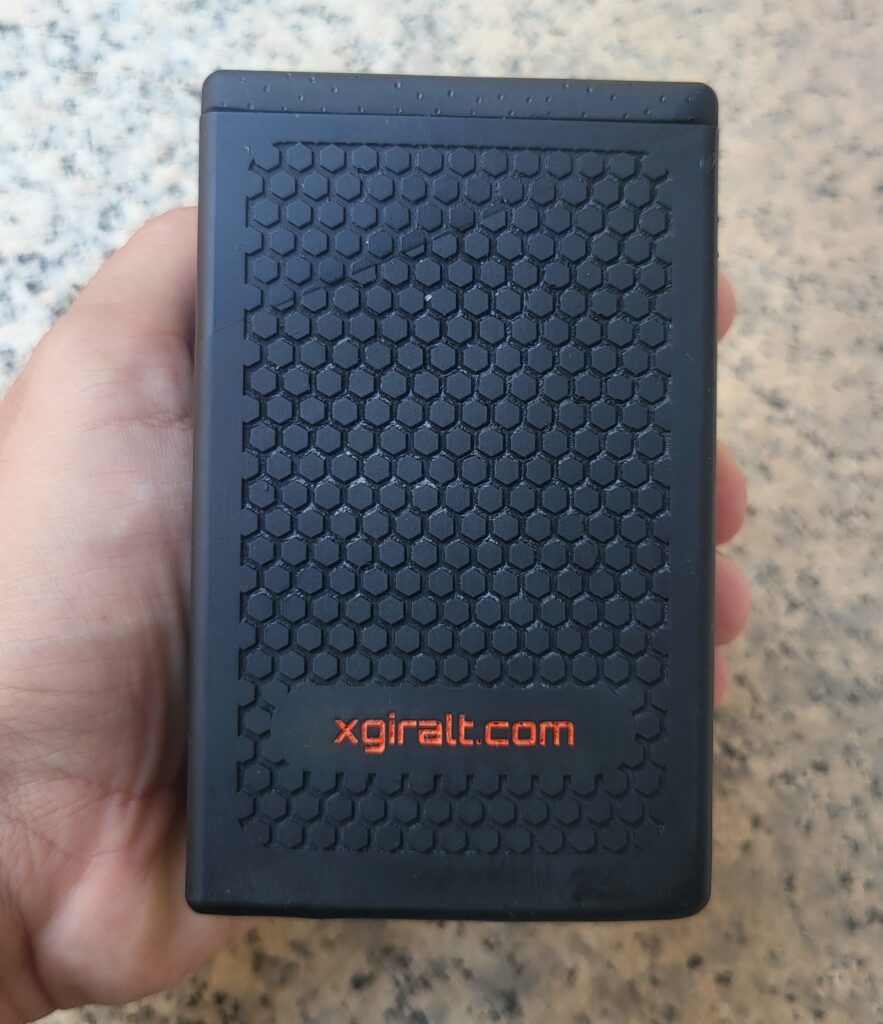
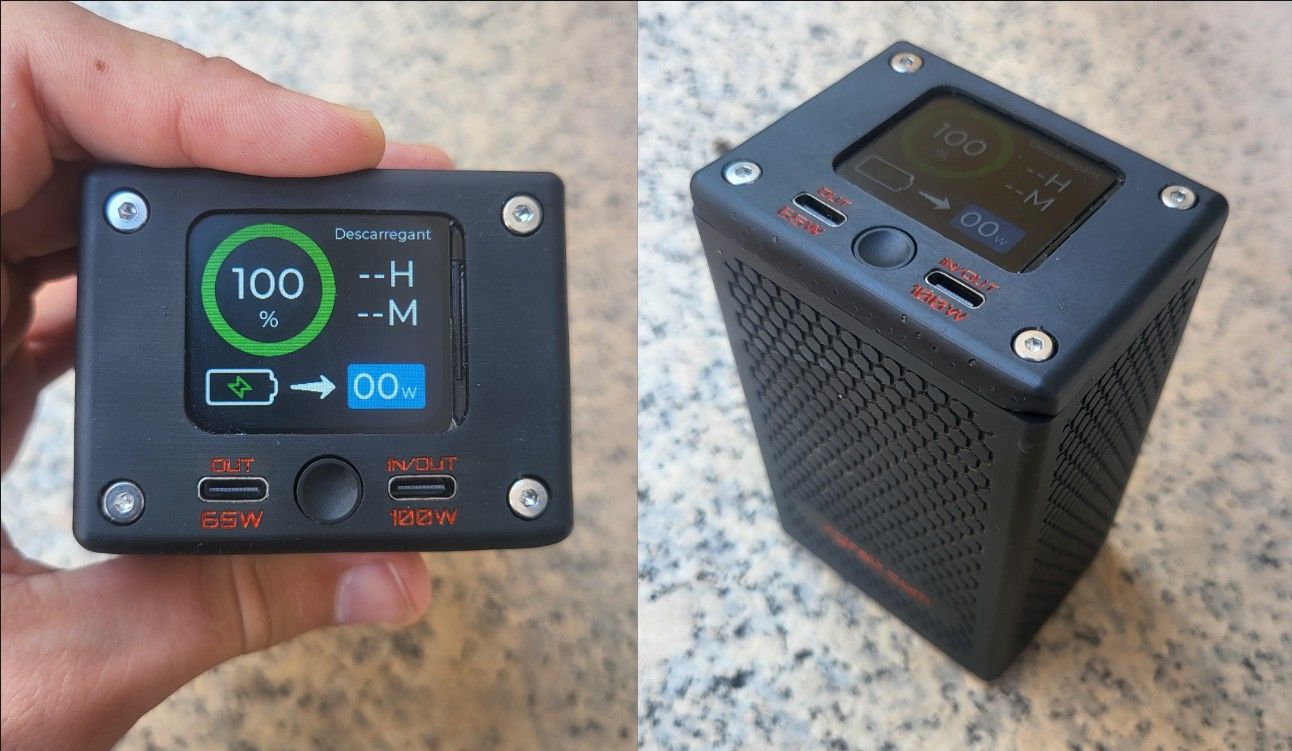
Final result